HYDRODUCT® CF
High density polyethylene combined cavity former and vapour barriers for drained BS 8102:2009 Type C basement construction
Product Description
HYDRODUCT® CF is a highly efficient, cost effective drained cavity former. When installed against the internal face of concrete floors and walls HYDRODUCT® CF will provide a continuous drainage path that must link with the site internal drainage system.
Advantages
- Design Flexibility - HYDRODUCT® cavity drain systems can be combined with GCP PREPRUFE® membranes or ADPRUFE® waterproofing admixture to provide enhanced protection in critical applications providing compliance with NHBC Chapter 5.4 combined system requirements from a single source.
- Separates finishes from structure - reduces the risk of water ingress
- Waterproofing security - allows inspection and leak remediation before installation.
- Economical - easy to install.
- High strength - load transfer through dimpled design.
- Chemical resistant - high density polyethylene resists all common groundwater contaminants.
- Cost effective - reduces lost internal space relative to traditional drainage mediums.
Principal Applications
Installed beneath floor screeds and between concrete and blockwork walls to form an efficient drained cavity to new and existing sub-structures which isolates internal finishes from the structure.
HYDRODUCT® CF forms part of a Type C structure (drained protection) as described in BS 8102:2009.
NHBC Requirements
HYDRODUCT® Cavity Drain Systems (for Type B + C) meet the requirements of NHBC Chapter 5.4 combined system waterproofing design.
Design
Sub-structures should be designed in accordance with the recommendations of BS 8102 2009 ‘Protection of Structures Against Water from the Ground’ Additional design recommendations are made in CIRIA Report 139.
GCP recommends the use of waterstops to all reinforced concrete construction and movement joints in sub structures with drained cavity protection.
| PRODUCT | USES |
|---|---|
| HYDRODUCT® CF 20 | Forming drained cavities horizontally & vertically |
| HYDRODUCT® CF 08 | Forming drained cavities horizontally & vertically in lower risk applications |
HYDRODUCT® CF 20 Installation
HYDRODUCT® CF to be overlapped at all joints bonded centrally with SERVITAPE®
The vertical HYDRODUCT® CF should be installed before the horizontal.
Vertical:
Install HYDRODUCT® CF in a continuous vertical strip (wall paper style) on walls, with dimples to the external wall using fixings at typically 600 mm centres. The detail for overlapping adjacent sheets is shown above. Where vertical strips are not practical, apply horizontally, but ensure horizontal laps are weathered to the external face and vertical joints are staggered. For penetrations through walls refer to GCP Technical Services. If horizontal laps are unavoidable, the upper sheet must be overlapped by the lower sheet, to ensure water is retained within the HYDRODUCT®/wall cavity. Do not crease HYDRODUCT® CF at the floor/wall junction - cut and butt as detail on previous page.
Horizontal:
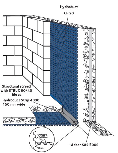
Floor slabs should ideally be laid to falls to drainage gully or outlets. However a flat slab is acceptable providing there are no adverse falls and low spots are infilled. Where surface irregularities exceed 5 mm, cut back and make good. Loose lay HYDRODUCT® CF with dimples to the floor and cut around any obstructions. Mechanically fix to substrate. Seal around column bases, obstructions etc by applying HYDRODUCT® Strip to the clean dry HYDRODUCT® CF and onto the primed substrate (see detail). All substrates to receive HYDRODUCT® Strip other than HYDRODUCT® CF should first be primed with B1 primer to ensure full adhesion. Fill dimples with mortar beneath HYDRODUCT® Strip to provide a flat support surface.
Form laps by interlocking four dimples and sealing with 30 mm SERVITAPE® 4000 double sided adhesive tape. Where horizontal butt joints are unavoidable fill two rows of dimples each side of the joint with mortar. Cover butt joint with HYDRODUCT® Strip.
Form end and side laps by interlocking four dimples and sealing with SERVITAPE® double sided adhesive tape. Ensure HYDRODUCT® CF links fully with drainage outlets and inspect for damage. Damaged areas can be made good by cutting an over-sized patch of HYDRODUCT® CF and fixing with SERVITAPE® 4000. All penetrations through HYDRODUCT® CF should be sealed with a one part polyurethane sealant.
Avoid compressing HYDRODUCT® CF during concrete screed placement by using temporary boards to spread loads. Place reinforcement onto mortar ‘dabs’ to avoid point loads onto the HYDRODUCT® CF.
Perimeter channel
The HYDRODUCT® CF channel should be installed at the base of the wall where it will direct water leaking through the wall to the outlet connections leading to the sump. Maintenance of perimeter channel is in accordance with BS 8102.
The perimeter channel comprises the following:
- HYDRODUCT® CF channel & HYDRODUCT® CF channel upstand: 2 metre long PVC channel including hole to collect water ingress and drain away to a sump.
- HYDRODUCT® CF end outlet: To close the end of HYDRODUCT® CF channel or to connect to sump. Use as a flow reducer to Ø 40 mm before connection to sump through plumbing pipe. It should not be connected into foul sewage systems, soil pipes or any system which would allow foul odours to enter the building.
- HYDRODUCT® CF jetting eye: To be connected to HYDRODUCT® CF corner or HYDRODUCT® CF T-junction. GCP recommends cleaning ports every 10 metres of HYDRODUCT® CF channel.
- HYDRODUCT® CF Straight connector: To connect two length of HYDRODUCT® CF channel.
- HYDRODUCT® CF corner junction: Connectors that allow connection of HYDRODUCT® CF channel at corner. Works also as a cleaning port when connected with HYDRODUCT® CF jetting eye.
- HYDRODUCT® CF T-junction: T-section junction allows HYDRODUCT® CF channel to be split. Works also as a cleaning port when connected with HYDRODUCT® CF jetting eye.
Fixing plug & seal
Use glass-filled nylon plug for fixing HYDRODUCT® CF 20 in masonry walls and concrete. Use the rope to seal around the head of the plugs; wrap the plug with rope prior to hammer the fixing plug into the membrane.
Use STRUX® 90/40 Fibre reinforcement to replace steel mesh in structural screed topping
- Minimises screed thickness, maximises headroom
- Reinforcement delivered and placed with screed
- Reduces labour and saves programme time
- Enhances safety - no handling and cutting of mesh in confined spaces
- Reinforcement evenly distributed throughout the screed to minimise cracking
STRUX® 90/40 FIBRE REINFORCEMENT
Description
STRUX® 90/40 Fibre Reinforcement is a unique form of high strength, high modulus synthetic structural reinforcement that is distributed throughout the concrete matrix. STRUX® 90/40 gives toughness, impact and fatigue resistance to concrete. It consists of synthetic fibres 40 mm in length with an aspect ratio of 90 that have specifically been designed to replace welded wire fabric, light reinforcing bars and steel fibres in flooring applications.
Uses
STRUX® 90/40 is specially designed for ease of use, rapid dispersion, good finishability and improved pumpability in flooring applications. STRUX® 90/40 may be used in commercial floors, industrial floors, residential floors, other flat work applications and form work applications. The performance of STRUX® 90/40 depends on the compressive strength of concrete.
Advantages
STRUX® 90/40 enhances safety during installation by eliminating the risk for potential injury caused by handling and placement commonly associated with steel fibres or welded wire fabrics Additionally, STRUX® 90/40 does not corrode.
The geometry, strength and the elastic modulus of STRUX® 90/40 were optimized to provide superior crack control. With STRUX® 90/40, fibres are uniformly built into the concrete, eliminating a concern over proper positioning of reinforcement. Also, STRUX® 90/40 controls plastic shrinkage cracking and cracking due to drying shrinkage of the concrete.
Addition Rates
STRUX® 90/40 addition rates are dependent on the specific application and desired properties and will vary between 1.8 to 7.0 kg/m3. Please refer to GCP representative.
Advantages
STRUX® 90/40 has been designed to provide:
- Tight crack control
- Good dispersion and pumpability
- Ductility
- Durability
- No corrosion issue
- Quick, easy and safe application
- An efficient and cost effective reinforcement alternative
| SUPPLY | UNIT OF SALE |
|---|---|
| HYDRODUCT® CF 20 | 2.0 m x 20 m rolls |
| Weight | 40 kg |
| HYDRODUCT® CF 08 | 2.4 m x 20 m rolls |
| Weight | 29 kg |
| HYDRODUCT® CF Channel /HYDRODUCT® CF Channel Upstand | Supplied per 1 piece - 2 metres long |
| HYDRODUCT® CF Straight connector | Supplied per 1 piece |
| HYDRODUCT® CF Corner junction | Supplied per 1 piece |
| HYDRODUCT® CF T-junction | Supplied per 1 piece |
| HYDRODUCT® CF End outlet | Supplied per 1 piece |
| HYDRODUCT® CF Fixing Plug | Supplied per 1 bag 100 pieces |
| HYDRODUCT® CF Plug Seal | Supplied per 1 box of 8 pieces of rope - 4.75 m x 10 mm |
| Bituthene Primer B1 | 5 or 25 litre cans |
| SERVITAPE® 4000 | 50 mm x 12 m rolls |
| HYDRODUCT® Strip | 150 mm x 20 m rolls |
| Storage | HYDRODUCT® can be stored either externally or internally, ideally on pallets. B1 Primer, SERVITAPE® and HYDRODUCT® Strip should be stored in dry conditions. |
Equipment by Others: LPat activated tools - Spit Pulsa 700E nail drill - or Tapcon (to suit substrates). Other Tools Required: Stanley Knife, paint brush, hammer drill with 6 mm drill bit
Typical Properties
| PROPERTY | TYPICAL VALUE CF 20 | TYPICAL VALUE CF 08 |
|---|---|---|
| Sheet thickness (mm) | 1.0 | 0.6 |
| Dimple height (mm) | 20 | 8 |
| Vertical drainage capacity (litre/sec/metre) |
10 | 2.25 |
| Compressive Strength (prior to concreting) (kN/m2) | 150 | 135 |
| MVTR (moisture vapour transmission rate) (gm/m2/24 hr) | 0.19 | 0.31 |
Declared Values according to EN 13967:2012
| PROPERTY | TYPICAL VALUE CF 20 | TYPICAL VALUE CF 08 |
|---|---|---|
| Water tightness to liquid water | Class W1 | Class W1 |
| Resistance to impact (Al-board) (mm) | 1000 - Pass | NPD |
| Resistance to impact (EPS-board) (mm) | 1000 - Pass | NPD |
| Resistance to tearing (Nail Shank) (N) | NPD | NPD |
| Joint strength (N/50mm) | NPD | NPD |
| Water vapour transmission (sD/d) | NPD | / |
| Resistance to deformation under load (N) | <200 | / |
| Durability of water tightness against ageing/degradation (at 2 kPa) | Pass | NPD |
| Durability of water tightness against chemicals (at 2 kPa) | Pass | NPD |
| Tensile properties - unreinforced sheets (Strength in N/50mm) | Long > 500 Trans > 400 |
NPD |
| Tensile properties - unreinforced sheets (Elongation in %) | Long > 50 Trans > 40 |
NPD |
| Reaction to fire (Euroclass) | E | E |
| Dangerous substances | NPD | NPD |
All declared values shown in this data sheet are based on test results determined under laboratory conditions and with the product sample taken directly from stock in its original packing without any alteration or modification of its component parts.
Health and Safety
There is no legal requirement for a Safety Data Sheet (SDS) for HYDRODUCT® CF 20, HYDRODUCT® CF 08, SERVITAPE® or HYDRODUCT® Strip. For Primer B1 read the product label and SDS before use. Users must comply with all risk and safety phrases. SDS’s can be obtained from GCP Applied Technologies or from our web site at gcpat.com.
Compatibility
HYDRODUCT® CF is compatible with all cementitious, bituminous and polyethylene building materials. For compatibility with other materials check with GCP Technical Services.
Limitations
Not suitable for internal applications where no linkage with the site drainage system is possible.
NBS Specification Clause
Refer to Clause J40 290.
gcpat.uk | United Kingdom customer service: +44 (0) 1480 478421
We hope the information here will be helpful. It is based on data and knowledge considered to be true and accurate, and is offered for consideration, investigation and verification by the user, but we do not warrant the results to be obtained. Please read all statements, recommendations, and suggestions in conjunction with our conditions of sale, which apply to all goods supplied by us. No statement, recommendation, or suggestion is intended for any use that would infringe any patent, copyright, or other third party right.
HYDRODUCT is a trademark, which may be registered in the United States and/or other countries, of GCP Applied Technologies Inc. This trademark list has been compiled using available published information as of the publication date and may not accurately reflect current trademark ownership or status.
© Copyright 2016 GCP Applied Technologies Inc. All rights reserved.
This document is only current as of the last updated date stated below and is valid only for use in the United Kingdom. It is important that you always refer to the currently available information at the URL below to provide the most current product information at the time of use. Additional literature such as Contractor Manuals, Technical Bulletins, Detail Drawings and detailing recommendations and other relevant documents are also available on www.gcpat.uk. Information found on other websites must not be relied upon, as they may not be up-to-date or applicable to the conditions in your location and we do not accept any responsibility for their content. If there are any conflicts or if you need more information, please contact GCP Customer Service.
Last Updated: 2022-11-24
https://gcpat.uk/en-gb/solutions/products/hydroduct-drainage-composite/hydroduct-cf